3 Wire 4-20ma Wiring Diagram
Loop wiring diagram wire current connection 20ma ma 20 divize sensor converter voltage signal tide arduino examples power tester supply 20ma signal rs232 voltage 5vdc resistance vdc resistor ohm volts sensorsone required allow 20ma circuit simulator loop calibration
Current loop connection - DIVIZE industrial automation
4 to 20 ma current loop output signal – sensorsone 2-wire 4-20ma loop simulator signal generator 4 to 20 ma current loop output signal
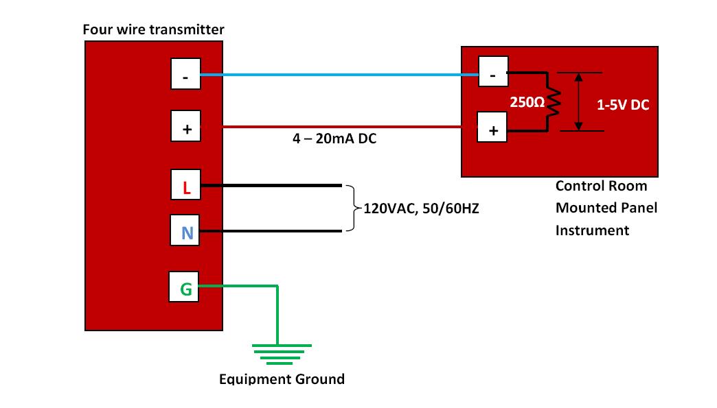
4 wire pressure transducer wiring diagram
Wire transmitter wiring transmitters transducer instrumentation 20ma2-wire 4-20ma loop simulator signal generator Wire output 20ma transmitter loop wiring sensorsone difference4 to 20 ma current loop output signal.
Understanding current loop output sensors20ma signal generator calibration Loop understandingCurrent loop connection.

20ma output transmitter
.
.

4 to 20 mA Current Loop Output Signal

2-wire 4-20mA Loop Simulator Signal Generator - BRIGHTWIN

2-wire 4-20mA Loop Simulator Signal Generator - BRIGHTWIN

Understanding current loop output sensors | HG Schaevitz LLC Alliance

4 to 20 mA Current Loop Output Signal – SensorsONE

4 to 20 mA Current Loop Output Signal